Kiln design
The kiln designed here was adapted from the New Hampshire Charcoal Kiln described by Henry Baldwin, New Hampshire State Forester, in 1950. Baldwin’s kilns were used extensively in pre-WWII New England charcoal making, most of which was aimed at producing fuel for residential cooking in East Coast urban apartment dwellings. The demand for charcoal for cooking was high during this time period because working-class city-dwellers often did not own modern cooking appliances or have access to other fuel sources.
New Hampshire kilns were used extensively for several decades in New England with excellent results. Often, several kilns were used together at a work site with different kilns operating at different stages of production at any point in time. This ensured a steady flow of work and continual production of charcoal for marketing. The kiln design shown here is similar to Baldwin’s, with some modifications. Generally the gauge steel used by Baldwin was heavier than that used here. This undoubtedly made his kilns more durable, but also less portable. For instance, Baldwin used a hand-operated boom for lifting the components of his kilns to load kilns on trucks and place them at the work site. In contrast, our design can be moved easily by hand. Second, Baldwin’s kilns were fabricated largely from basic materials, mostly sheet metal, cut, rolled, and assembled by welding. Our version uses pre-fabricated components made from medium gauge galvanized or painted sheet metal. This reduces the labor and cost as compared with making a kiln from scratch. Further, our approach requires only a few simple skills and tools that many potential kiln builders probably already possess.
The kiln consists of three main components, the base, body, and bonnet (Figure 1). Conveniently, these parts are sold together as ready-to-assemble bulk bins commonly used for feed storage in livestock operations. The intended use of bulk bins has them inverted from what is shown in the Figure 1. What was designed to be the pour-spout of the bulk bin serves conveniently as the kiln’s cap here. The base, body and bonnet of the kiln are not permanently fastened together, except by a temporary bead of heat-resistant mortar between the kiln body and bonnet used during kiln operation to reduce air leakage. The weight of the kiln and a slight overlapping lip on the kiln base ensures a nearly airtight fit, but a bead of sand or heat-resistant mortar can be placed in the lip to improve air tightness. The cap slides open, which assists loading and lighting of the kiln, but most of the time it is closed during kiln operation.
Several modifications allow the bulk bin to function effectively as a charcoal kiln (Figure 1). A series of dual-purpose damper/exhaust holes are cut at even spacing around the base of the kiln (A). We cut eight, 6” diameter holes, although the exact number and size is not critical. A C-shaped bracket (C) is attached to the kiln around each of the damper holes. These brackets are made of two thicknesses of sheet metal and provide a means of attaching exhaust stacks (B) and damper covers (D) over the holes. A close-up of the mounting bracket shows details of its design (Figure 2). Three narrow strips of sheet metal (shaded in Figure 2) are fastened to the outer edges of the bracket. Once the bracket assembly is fastened to the kiln these strips provide a slight gap between the kiln body and C-bracket. A flange collar on the exhaust stack elbow is slipped into this bracket to connect the stacks to the kiln. Damper covers, which are simply small square pieces of sheet metal with handles attached, are slid into the brackets to cover the holes where air restriction is required (Figure 3).
Figure 1. Modified New Hampshire charcoal kiln developed and tested at Virginia Tech.
Figure 2. Detail of exhaust stack mounting bracket made from sheet metal. Side shown faces kiln body and is attached by nine small bolts.
The flange and C-bracket mounting system allows the operator to attach or remove stacks as needed to control the progress of the burn during charcoaling. Damper covers likewise allow the control of airflow through the kiln. Removable stacks and adjustable dampers are important to the kiln design as they substantially improve the portability of the system, and they are essential for its efficient operation.
Dimensions
Once assembled from the bulk bin kit, the kiln body we used is 55” in diameter and 43” tall. The body comes in two cylindrical sections, each roughly 22” tall that are bolted together, one atop the other, with hardware provided in the kit. Presumably, a person could build a taller kiln by adding more sections to the body; however, we have found that the 43” height is convenient for loading and moving the kiln from place to place. Note that most full-sized pickup truck beds are 48” wide, so the kiln body can be laid on its side and rolled onto the truck bed with a few inches to spare on either side. The bonnet rises an additional 26” above the rim of the kiln body, with the cap positioned on a flat circular platform roughly 17” in diameter. This entire cap assembly is provided with the pre-fabricated bulk bin kit. The kiln base is concave or saucer-shaped, adding approximately 6” of additional height to the kiln’s dimensions. Based on these dimensions, the kiln’s volume capacity is roughly 79 ft3, or about 6/10ths of one cord. Of course, the exact capacity of any batch will depend on how tightly wood is packed into the kiln during loading.
Six-inch exhaust and air port dimensions were used to take advantage of the wide range of parts and accessories available for 6” stovepipe. One exhaust stack uses two 24” sections, one 12” section and one 90O elbow. The 12” sections in the exhaust stacks (E, Figure 1) house catalytic converters for reducing air pollution during charcoaling. Six-inch diameter disc-shaped catalytic converters are available from many heating supply dealers or woodstove retailers and can be easily mounted in the 6” diameter flue pipe. The catalysts are quite simple to use, and reduce air pollution from charcoal making considerably. While they add a modest cost to kiln construction and operation, they are durable for long-term use and can be moved from one kiln to another during the period of charcoaling where smoke is produced. Thus, a set of four catalysts is sufficient to service four kilns operating on a 36-48 hour (or longer) sequence of operation.
We’ve found no advantage to permanently fastening exhaust stack sections together. They can easily be connected and disconnected as needed without fasteners. Female-male fittings on stovepipes and elbows provide sufficient stability of stacks during operation. If needed, a length of safety wire can be attached to the kiln body using a self-tapping sheet metal screw. The wire can then be looped around the stack to provide additional support, for example, when operating the kiln in windy conditions.
When mounted to the kiln body, the C-shaped mounting brackets will take on the curvature of the cylinder. For easy insertion into the brackets and snug fitting around the exhaust holes, flange collars and damper plates can also be curved slightly when fabricated (Figure 3). Damper plates and the flange collars are 8” x 8” to fit snugly inside the 8.5” C-bracket openings (Figure 4).


Figure 3. Flange for attaching exhaust stovepipes to kiln C-brackets (left) and damper plate (right).
Figure 4. Mounting bracket dimensions.
Hardware
Most hardware for assembling the kiln is included with the bulk bin kit, but some additional fasteners will be needed. Each of the eight mounting brackets requires nine fasteners. We used ¾” length, ¼ -20 machine screws with one flat and one locking washer. Approximately twenty-five self-tapping sheet metal screws per kiln can be used to close any gaps in seams that would otherwise leak air. A few small sheet metal scraps or washer-fitted machine screws must be fastened over pre-drilled holes around the top rim of the kiln body to seal the holes.
Tools
Most of the kiln fabrication can be accomplished using the following (required) hand tools:
- tin-snips or sheet metal shears;
- locking pliers;
- sheet metal hand crimper/bender;
- ball peen hammer;
- various nut and screw drivers;
- tape, stick ruler and carpenters’ square;
- drill and bit set with marker punch;
- hand file and wire brush.
Construction can be sped up by using any of the following (optional) tools:
- pneumatic sheet metal shears;
- pneumatic sheet metal nippers;
- bench grinder and wire-wheel brush;
- sheet metal table shear;
- sheet metal brake;
- sheet metal pinch roller;
- hydraulic hole punch;
- medium duty spot welder.
Photographs
Several photographs help illustrate various steps in construction. Figure 5 shows the kiln body and bonnet components assembled but unmodified from the pre-fabricated bulk bin kit design. The lower half of the body section is shown with exhaust/damper holes cut out and mounting brackets installed in Figure 6. A close-up of an exhaust flange assembly is shown in Figure 7. We’ve used several different versions of the flange assembly. The one shown is relatively easy to build, durable and rigid when attached to the kiln.
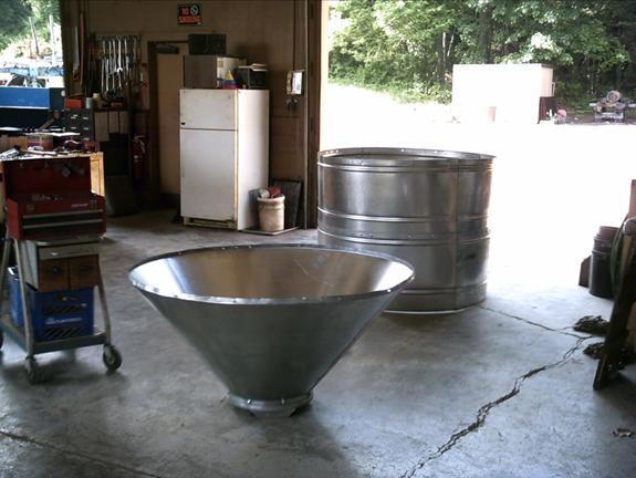
Figure 5. Kiln body and bonnet unmodified from pre-fabricated bulk bin kit.
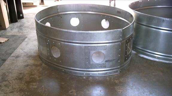
Figure 6. Lower body section with cutout holes and C-brackets installed.
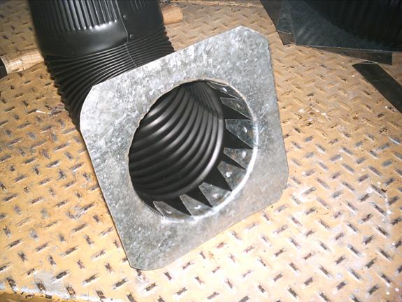
Figure 7. Detail of exhaust flange and elbow assembly.